


Pre-load Electromechanical Lock A1-SA-ZD
Description
We are pleased to introduce the new A1-SA-ZD lock. It is a high performance and security, pre-load electromechanical lock.
It is fail safe, so the bolt will retract when the power is interrupted (even under a pre-load of up to 1200N, unique to the A1-SA-ZD).
Pre-load Electromechanical Lock A1-SA-ZD
Technical characteristics:
- Voltage 24V DC
- Consumption 2,35A activation current – 130mA holding current
- Principle Fail safe (= unlocked without power)
- Backset n/a (without cylinder block)
- Direction Both L and R – symmetrical bolt for both bumper doors and revolving doors
- Unlocking Access control makes contact between pin 2 and 3 on the lock, the bolt retracts by spring force
- Automatic locking Electrically, each time the door closes
- Panic function There is no handle, so not according to EN 179. The bolt will retract when the power is interrupted (even under a pre-load of up to 1200N)
- Signalisation Position of the door (open/closed) and position of the bolt (unlocked/locked), transistors switch actively to GND (24VDC/max. 100mA)
- Resistance of the bolt 40’000N side load (measured directly on the bolt)
- Throw of the bolt 20mm (in less than 100 milliseconds)
- Temperature resistance range -25°C to +70°C
Dimensions
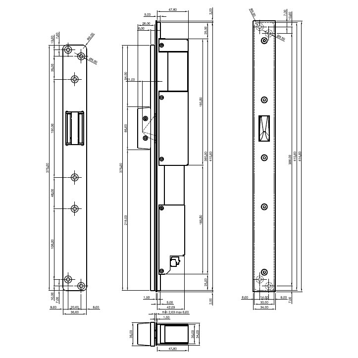
This Pre-load Electromechanical Lock has been manufactured to be operated by different impulse generators: push buttons, numeric keypads, card readers, key contacts, timers, etc. These should be equipped with a Normally-Open contact.
These locks are mortise locks. The hardened duplex bolt, as well as the deadlock, are mounted on a solid baseplate. This baseplate is made of stainless steel (AISI 304, cast according to the lost-wax process). The stainless steel covers (AISI 304) provide a closed case.
The included striker plate in stainless steel has a moulded striker cup with rollers for limited friction during the retraction of the bolt.
The control system integrated in the lock provides for automatic locking when the door closes. The lock detects the striker plate by means of 3 Hall-sensors on the printed circuit board (which is protected against humidity etc. by a polyurethane casted resin). Subsequently, the bolt is ejected by a single acting solenoid and instantaneously blocked by the deadlock (acivated by a second solenoid). The lock will now switch from activation current to holding current. To unlock, contact must be made between terminal clamps 2 and 3. Subsequently, the current to the solenoids is interrupted by the internal printed circuit board, causing the bolt to be retracted by means of springs. The bolt will remain retracted until the door closes and the striker plate has been detected (when no permanent contact is made between the 2 terminal clamps mentioned before). If the door is not opened after the unlocking impulse, the lock will automatically relock after 4 seconds.
In case of power failure, the lock will remain in or go to the unlocked position.
Due to its symmetrical bolt, the door can be used both left and right. These locks are usually integrated in the door frame in order to avoid the use of a cable transfer (in this case, the striker plate is integrated in the door leaf). These locks can also be installed horizontally, with the bolt pointing downwards. This lock can be used in combination with automatic door openers.
These electric locks should always get continuous power supply. That will ensure that they retain their intelligence and therefore will know their position.
Signalisation is provided with regard to the position of the bolt (locked – unlocked) and the position of the door (closed – open). These contacts switch to GND when activated (24VDC/max. 100mA). Furthermore, these locks are suitable for high frequency use and can be activated continuously. For the proper functioning of the lock, a specific cable must be used: 2 x 1,5mm² (power cable) + 5 x 0,22mm² (signalisation wire); shielded (order separately with reference: BB25LSZH). For the proper functioning of the lock, a specific power supply must be used: 24V DC; 2,5A stabilised power supply (order separately with reference: PS24D52). For the proper functioning of the lock, the distance between the lock and the power supply should be maximum 25m (this to avoid too large a drop in power supply on the cable).
For more information on the power supply and cable, click here.


